18. Philadelphia or Chicago – Level Rods
By Gordon Olsson
Two types of level rods have been well recognized for years – the Philadelphia rod and the Chicago rod. The Philadelphia rod is a sliding (telescopic) rod that extends to various lengths (12 to 16 feet). The Chicago rod is available with three or four sections that are attached to each other by a slip joint. The sections are kept in separate compartments in a canvas bag when not being used.
Despite new technology, level rods are still used today although not to the extent as in the past. It is intriguing to note the wide variety of rod types that are shown in old survey instrument catalogues, many named after localities. Rods were not difficult to manufacture so it can be assumed it was easy to cater to local needs or idiosyncrasies. Old survey instrument catalogues show well over twenty different types of rods. To name a few: architect’s rods, mining rods, Philadelphia rods, Chicago rods, California rods, Frisco rods and Carstaff four-fold stadia rods. Some types of these had inverted graduations and numbered for use with inverted reading instruments. After the metric system was adopted in Canada in the 1970s, metric rods also came on the market.
Invar Precise Leveling Rods were used when the greatest possible accuracy was required. The co-efficient of expansion of invar steel is so small that it can be neglected. Les Frederick, ALS (Ret.) who in 1977 did first order leveling for the Ontario Department of Highways recalls: “The invar rods for first order leveling came in a set of two. While readings were taken on one rod the other was being set up and accurately plumbed. The level used had a micrometer which enabled readings to 0.1mm.”
When accuracy was not of primary importance and space was an issue, there were also flexible cloth (or canvas) tape rods. When used, they could be attached to a pole obtained in the field or a range pole. When not used, they could be rolled up taking very little space.
Rods can be self-reading where the person using the level, records the elevation reading on the rod. Other rods have a target which is moved up and down the rod according to directions from the person on the level with the person holding the rod recording the reading.
Often a level bubble is attached to the rod to keep it vertical. Waving the rod is a technique that can also be used. Waving involves moving the rod, so that the top is waved back and forth between a slight incline towards the level and a slight incline away. The movement is repeated a few times with the person using the level recording the smallest reading as that is when the rod is most vertical.
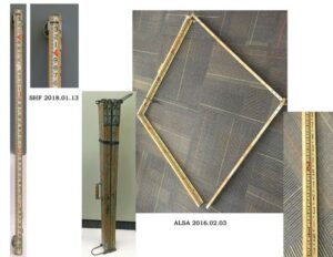
On the left is a Philadelphia rod. It is telescopic, extendable to 12 feet and graduated in feet and one hundredth of a foot.
Ed Scovill Estate
SHF 2018.01.13
The three images on the right show a 14-foot-long folding rod. It is graduated in feet and one hundredth of a foot.
Donated by Don Dawson ALS#157
ALSA 2016.02.03.
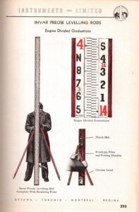
Image of an Invar Precise Leveling Rod in Instruments (1951) Limited Catalogue. The catalogue belonged to J.B. Underwood and Associates Limited, Edmonton.
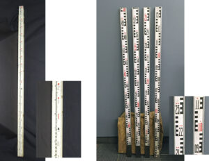
In the image on the left is a three-section, five-metre-long aluminum telescopic Philadelphia rod. The decimetre and centimetre marks are coloured black, and the metre marks are coloured red. Metre sections are designated by red dots above the number – the first metre has no dots, the second has one dot, the third has two dots, and so on. This marking system facilitates reading the rod when the metre mark is not in the field of view of the instrument. Because the length of an aluminum rod is affected by temperature, there is a label on the top back side of the first section that states the temperature correction to be applied to the length of the rod.
Donated by Grant Cross ALS (Ret.)
ALSA 2008.10.23
On the right is a five metre, four section Chicago rod. The sections of the rod are attached to each other by inserting the insert of one section into a sleeve on the abutting section. The rod is graduated in one-centimetre intervals. Decimetre and centimetre numbers are coloured black with decimeter numbers marking half metre and full metre numbers coloured red. Similar to the rod shown on the left, metre sections are designated by red dots. The four sections of the rod are housed in a khaki coloured four-pocket bag. (See the image behind the four rod sections.)
Reg Watson Estate
SHF 2015.01.52
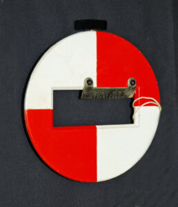
Level rod target. This target is about 12 centimetres in diameter. The edge of the opening has a graduated scale to facilitate reading the rod. There is a black knob on the left side that is used to clamp the target to the rod. Each type of rod would require a target designed for it.
Donated by Gordon Koshman
ALSA 2010.07.06.
All of the above rods are used for the process of determining differences in elevation. Rods are also used to measure distances without needing to physically measure the distance on the ground. Stada rods were commonly used for topographic surveys where high accuracy was not required. Subtense bars which are held horizontal apply similar geometry as the stadia method to determine distance. By reading vertical angles both stadia rods and subtense bars can also be used to determine differences in elevation.
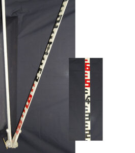
Folding stadia rod. It is 15 feet long with markings in feet and tenths of a foot. The graduations would have been tricky to read – it appears that the point on the mark between the foot numbers marks .5 of a foot. The first five feet and last five feet marks are coloured black and the middle five feet marks are coloured red.
Donated by Grant Cross ALS (Ret.)
ALSA 2008.10.21
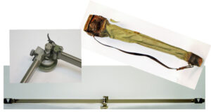
Subtense bar. Made by Wild Heerbrugg. Inscribed No. 138061. The distance between the two targets at the ends of the bar is two metres. It mounts on a standard Wild tribrach. Subtense bars usually were made with a stable material such as invar. They were used to measure short distances indirectly. The horizontal angle between the two targets is read using a theodolite. The distance from the theodolite to the subtense bar is calculated using trigonometry. The vertical angle is also read so the distance can be converted to the horizontal. They were more popular in Europe than in North America, with one application being measuring distances across high traffic areas.
Donated by Peter Walker ALS#498
ALSA 2006.14.01
Sources of Information:
- Breed and Hosmer, Elementary Surveying, Eight Edition, 1945.
- The 1958 Hughes-Owens Company (Limited) Catalogue’58.
- Instruments (1951) Limited Catalogue No.57.
- Smithsonian National Museum of American History
Author: Gordon Olsson, ALS (Hon. Life)
April 1, 2022
Updated: August 30, 2024
Copyright 2024 © Alberta Geomatics Historical Society
