

22. A Dying Art – Drafting Becomes Impersonal
By Gordon Olsson
In Article 19, There were no Stories about Drafting, it was stated that drafting survey plans required knowledge, skill, experience and an artistic flair. Drafters added a personal touch to their plans by adding decorative features such as unique north arrows, hand lettering was individualistic, and the look and placement of title blocks was decided by the drafter.
Around the mid-20th century, mechanical drafting aids came on the market. Lettering sets, such as the Leroy, enabled drafters unskilled in hand lettering to produce clear standardized lettering. Electric erasers with erasing shields enabled mistakes to be erased easily. Tabletop drafting machines replaced protractors and set squares. Regulatory bodies started to place more emphasis on standardizing abbreviations, symbols for monuments and the look of north arrows. Sample plans were provided that standardized the look and placement of title blocks, endorsements and such.
Mechanical drafting aids in the Alberta Geomatics Historical Society collection are illustrated below. Eventually, they would all be supplanted by computer-aided design (CAD).
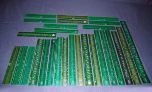
This set of 27 Wrico lettering templates was made by The Wood-Regan Instrument Co., Nutley, N.J. The set includes templates of a variety of sizes for letters, numbers and symbols. They never gained wide acceptance by survey drafters.
Donated by Dave Williams, ALS (Ret.)
ALSA 2008.14.23
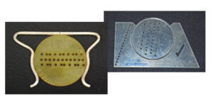
Lettering Guides. These were used for drawing parallel guidelines on the drawing surface for lettering. The guide on the left is comprised of a metal frame with a circular plastic guide that can be rotated in the frame to draw lines at different distances apart. The guide on the right is a newer model where the outer frame is comprised of plastic. Both are called “Ames Lettering Guide” and are made by Olsen MFG Co, Ames, Iowa, USA. The one on the left with the metal frame was patented in 1918.
Donated by Dave Williams, ALS (Ret.)
On the left ALSA 2008.14.34
On the right ALSA 2008.14.33
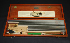
K&E Leroy Lettering Set. Lettering sets such as this one were marketed from the 1940s, although they were not fully adopted for drafting survey plans until a few decades later. This lettering set contains six templates, one scriber, seven pen nibs (each for a different width of line), and a pen nib holder. The outlines of a letter on the templates are traced by one arm of the scriber. The other arm with the pen nib duplicates the letter on the drawing surface. The pen nib holder was used for drawing straight lines. Leroy lettering sets were widely used. This was a basic set. Other sets included a larger variety of templates and pen nibs
Estate of Ed Scovill.
SHF 2018.01.06
The Unitech lettering set was another popular lettering set that replaced free hand lettering. This one was used by Brown, Okamura & Associates Ltd.
Donated by Dave Williams, ALS (Ret.)
ALSA 2008.14.18
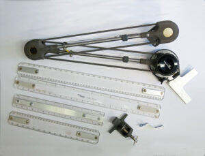
Mutoh Drafting Machine. Tabletop drafting machines have arms that can be set on any bearing which facilitated plotting boundary lines. Mutoh is the name of a Japanese company. The plastic arms are labeled PiCo Design Germany.
Ed Scovill Estate
SHF 2018.01.07
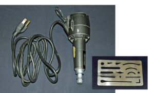
Electric Eraser and Erasing Shield. The electric eraser used in conjunction with an erasing shield allowed ink to be removed with no or minimal damage to the drawing surface which was usually linen. These items were used by Brown Okamura & Associates Ltd.
Donated by Dave Williams, ALS (Ret.)
Electric Eraser ALSA 2008.14.21
Erasing Shield ALSA 2008.14.35
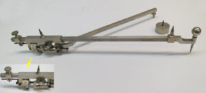
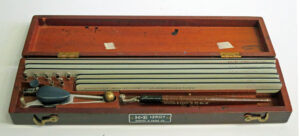
Planimeter made by Stanley, Great Turnstile, Holborn, London.
The planimeter was a mechanical device that was used well before the mid-20th century. Determining the area of surfaces bounded by natural boundaries could be a challenge without it. One could divide an area into rectangles and triangles of which the area of each could be calculated and then all totaled, however that was time consuming and not very accurate. In 1818, Johann Martin Hermann, a Bavarian surveyor, built the first planimeter, a mechanical device which enabled the operator to obtain the area of a closed surface by tracing around its boundaries.
The maker of the planimeter shown above, W.F. Stanley and Company Limited, was a drawing instrument maker that traded at Great Turnstile from the 1900s to 1914. To use it, the operator sets the anchor arm, either by pressing the needle point of the anchor arm into the drawing surface or anchoring it on a small circular weight. The user then sets the tracing arm to the graduation that is usually provided with the planimeter for the scale of the plan, zeros the recording wheels, then with the pointer, traces the boundary clockwise all around the parcel. The area can be determined by applying a conversion factor obtained from a scale chart to the reading on the planimeter. Some planimeters allow settings which enable the area to be read directly on the dial. A simple method of using a planimeter to calculate an area is to trace the pointer around a known area, which can be a simple square drawn to the same scale as the plan. A conversion factor can then be determined which can be applied to a reading obtained by tracing around the parcel for which an area is required.
Donated by C.H. Weir, ALS#164.
ALSA 2007.28.03
Sources of Information:
- National Museum of History, Planimeters: https://americanhistory.si.edu/collections/object-groups/planimeters
- Science Museum Group, W.F. Stanley and Company Limited: https://collection.sciencemuseumgroup.org.uk/people/cp1655/w-f-stanley-and-company-limited.
- Erica L. Wood-Bedi Lettering the Old-Fashioned Way, TechTrends – May/June 2013.
Author: Gordon Olsson, ALS (Hon. Life)
May 31, 2022
Copyright 2024 © Alberta Geomatics Historical Society